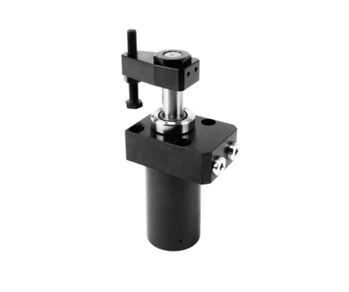
Swing Clamps with Sturdy Swing Mechanism
double acting, max. operating pressure 350 bar
Hydraulic swing clamps are used for clamping of workpieces, when it is essential to keep the clamping area free of straps and clamping components for unrestricted workpiece loading and unloading.
Due to the sturdy swing mechanism and the manifold possibilities of position monitoring these swing clamps are particularly suited for
- Automatic manufacturing systems
- Clamping fixtures with workpiece loading via handling systems
- Transfer lines
- Test systems for motors, gears and axes
- Assembly lines
- Special machine tools
The hydraulic swing clamp is a pull-type cylinder where a part of the total stroke is used to swing the piston. The favourable area ratio (piston/piston rod) allows high clamping forces already at relatively low oil pressures.
Due to the sturdy swing mechanism the angle position of the clamping arm remains the same after a slight collision with the workpiece during loading
or unloading. Also a collision during the clamping process is not critical.
When using high flow rates the swing speed is limited by installed throttle points. For connection via drilled channels, adjustable throttle valves can be screwed instead of the screw plugs. The FKM wiper at the piston rod can be protected against coarse and hot swarf by an optionally available metallic wiper.
| Item no. | CAD data | functioning | piston diameter [mm] | rod diameter [mm] | max. pulling force [kN] | |
|---|---|---|---|---|---|---|
|
Item no.
|
CAD data
|
Properties
| ||||
|
Item no.
|
CAD data
|
Properties
| ||||
|
Item no.
|
CAD data
|
Properties
| ||||
|
Item no.
|
CAD data
|
Properties
| ||||
|
Item no.
|
CAD data
|
Properties
| ||||
|
Item no.
|
CAD data
|
Properties
| ||||
|
Item no.
|
CAD data
|
Properties
| ||||
|
Item no.
|
CAD data
|
Properties
| ||||
|
Item no.
|
CAD data
|
Properties
| ||||
|
Item no.
|
CAD data
|
Properties
|
| Item no. | CAD data | Description |
|---|---|---|
|
Item no.
|
CAD data
|
Description
Nut M28 x 1.5 mm
as per data sheet B1.880
|
|
Item no.
|
CAD data
|
Description
Nut M35 x 1.5 mm
as per data sheet B1.880
|
|
Item no.
|
Description
Nut M14x1.5
as per data sheet B1.852
|
|
|
Item no.
|
Description
Nut M20x1.5
as per data sheet B1.852
|
|
|
Item no.
|
CAD data
|
Description
Clamping arm without thread
for series 1843
max. 350 bar, as per data sheet B1.852
|
|
Item no.
|
CAD data
|
Description
Clamping arm without thread
for series 1844
max. 350 bar, as per data sheet B1.852
|
|
Item no.
|
CAD data
|
Description
Clamping arm without thread
for series 1845
max. 350 bar, as per data sheet B1.852
|
|
Item no.
|
CAD data
|
Description
Clamping arm without thread
for series 1846
max. 350 bar, as per data sheet B1.852
|
|
Item no.
|
CAD data
|
Description
Clamping arm without thread
for series 1847
max. 350 bar, as per data sheet B1.853
|
|
Item no.
|
CAD data
|
Description
Flow control valve G1/8
as per data sheet B1.8500
|
Take advantage of the free benefits of our login area:
- CAD data download
- Download operating instructions
Welcome back! Log in to your already existing user account.
