Hinge clamps (9)
Application
Hydraulic hinge clamps are used for clamping of workpieces, when it is essential to keep
the clamping area free of straps and clamping components for unrestricted workpiece loading and unloading.
Function
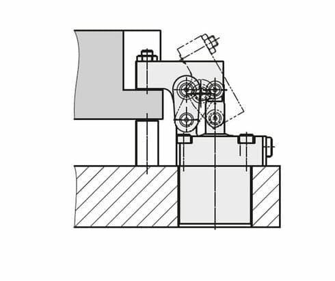
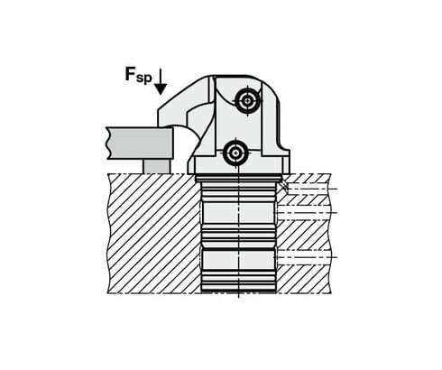
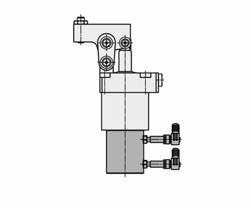
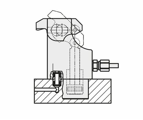
The hinge clamp is a double-acting hydraulic cylinder with integrated clamping lever. When
pressurising the element, the piston moves upwards and swivels the clamping lever over
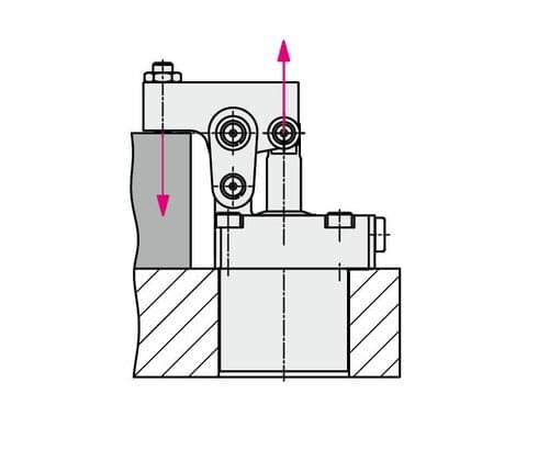
a hinge forwards and at the same time downwards onto the workpiece. The piston force is
deviated by 180° and, depending on the lever length, the force is available as clamping force.
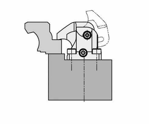
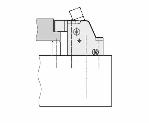
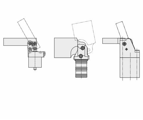
The compact clamp is a double-acting pulltype cylinder where a part of the linear stroke is used to swing the clamping lever onto the workpiece. The piston pull force is directly converted to clamping force less the friction losses.
The flat lever clamp is available single or double acting. The piston moves upwards against the rear edge of the clamping lever and swivels the clamping lever to the clamping position. The piston force is deviated by 180° onto the workpiece. When unclamping the fl at lever clamp, the clamping lever is swivelled back to the off-position by means of a hook-shaped carrier on the piston.
Workpiece clamping without any side loads
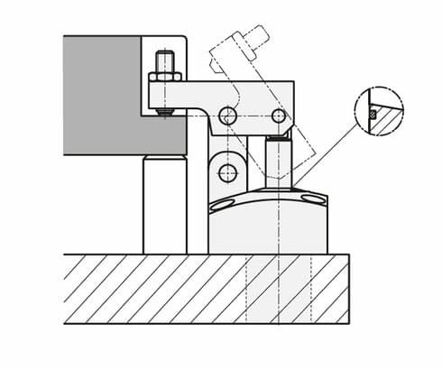
The hinge clamp allows clamping without side loads, if the clamping point is exactly on the
height of the pivot point of the lever. If the clamping point is within the indicated clamping range, the side load can be neglected.
In the case of the compact clamp, no side load can occur, since the clamping lever moves
only vertically in parallel to the piston axis. Swinging away of the clamping lever is only made outside the usable clamping range.
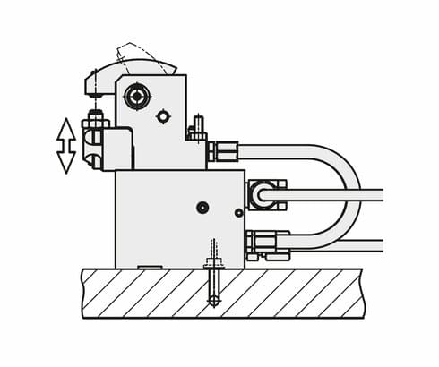
Clamping height and clamping range
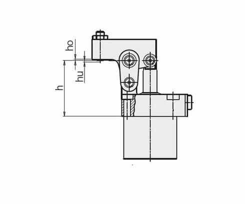
On the data sheets of the hinge clamps, the optimum workpiece height h is indicated.
At this height, the clamping force acts exactly vertically onto the workpiece.
The clamping range (ho + hu) is practically the tolerable deviation of the workpiece height.
The clamping lever has still a suffi cient stroke reserve.
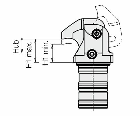
For the compact clamp, there is no optimum workpiece height, since the clamping
lever moves in a straight line within the usable clamping range. The indicated minimum and maximum workpiece height must be kept.
Longer or shorter clamping levers
When using longer clamping levers naturally reduces the clamping force.
When using shorter clamping levers, the hydraulic pressure must be reduced so that the lever mechanism is not overloaded.
For the calculation of clamping forces and the permissible operating pressure can be found on the data sheets and formulae on the data sheets.
Accessory Long clamping lever
Long clamping levers are available as accessory or as an option for all types of hinge and compact clamps. The clamping levers can be manufactured from these blanks in the desired shape or length.
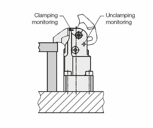
Accessory Position monitorings
Two series of the hinge clamps are optionally supplied with an extended piston rod
(switch rod). A pneumatic or inductive position monitoring can be fi xed at the bottom of the housing.
Both versions have the following control functions:
- Unclamped
Piston retracted and clamping lever in off-position. - Clamped
Piston extended and clamping lever in clamping position.
For each control function, a pneumatic line or an electrical line has to be provided at the clamping fixture.
The double-acting flat lever clamps are supplied with bore hole for the pneumatic monitoring of the clamping lever as standard.
The customer can decide for himself if he wants to use the two connections.
The compact clamps can optionally be supplied with bore holes for the pneumatic monitoring of the clamping lever.
For the cartridge type, either the clamping or the unclamping monitoring can be selected.
The flange type can be supplied with both monitorings.
- Unclamped
The clamping lever is within the unclamping range,
starting approx. 10° before the final position. - Clamped
The clamping lever is within the usable clamping range
and the workpiece is clamped with minimum clamping force.
For the last-mentioned function, a minimum pressure of 70 bar is required.
Metallic wiper edge
The hinge clamps and the compact clamps are provided with a metallic wiper edge at the piston rod outlet. Thus, the subjacent FKM wiper is protected against hot swarf or high coolant pressure.
For dry machining and minimum quantity lubrication as well as in case of accumulation of very small swarf, the hinge clamps should be regularly cleaned and lubricated.
Sealing materials
- NBR = Nitril-Butadien-Rubber
Trade name e. g. Perbunan
Operating temperature – 30 … + 80 °C - FKM = flour caoutchouc
Trade name e. g. VITON®
Operating temperature – 20 … + 150 °C
Maximum operating pressure
This pressure specifi cation is valid for the use of the standard clamping lever.
The admissible operating pressure for other lever lengths can be determined with the
clamping force diagrams on the data sheets
Admissible flow rate
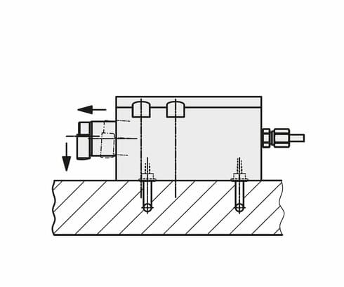
The catalogue specifi cations should not be exceeded to avoid overload and increased wear. A throttling of the flow rate has to be made in the oil supply line to the hinge clamp to rule out a possible pressure intensifi cation.
Note
The hinge clamps B 1.8268 have a built-in flow control valve that can be easily adjusted from above.
Leakage rate
Static under pressure, all clamping elements are leakage-free.
When extending the piston, the sturdy high-pressure seals let pass a little residual oil film. This increases the service life of the seals and guides.
Bleeding
Air in the oil prolongs the clamping time considerably and leads to function troubles. Therefore, thorough bleeding has to be effected during start up.
Take advantage of the free benefits of our login area:
- CAD data download
- Download operating instructions
Welcome back! Log in to your already existing user account.
