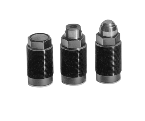
Threaded-body cylinders
max. operating pressure 500 bar
These threaded-body cylinders can be threaded directly into tapped holes in the fixture down to the hex-section of the cylinder body. Spacings between cylinders can be minimised when cylinders are arranged in a row, since the oil is fed through drilled passages in the fixture.
Sealing is made with the supplied sealing ring at the bottom of the location hole.
A long piston guide in combination with an O-ring/back-ring seal provides trouble-free
operation.
| Item no. | CAD data | stroke [mm] | functioning | piston diameter [mm] | rod diameter [mm] | |
|---|---|---|---|---|---|---|
|
Item no.
|
CAD data
|
Properties
| ||||
|
Item no.
|
CAD data
|
Properties
| ||||
|
Item no.
|
CAD data
|
Properties
| ||||
|
Item no.
|
CAD data
|
Properties
| ||||
|
Item no.
|
CAD data
|
Properties
| ||||
|
Item no.
|
CAD data
|
Properties
| ||||
|
Item no.
|
CAD data
|
Properties
| ||||
|
Item no.
|
CAD data
|
Properties
| ||||
|
Item no.
|
CAD data
|
Properties
| ||||
|
Item no.
|
CAD data
|
Properties
|
| Item no. | CAD data | Description |
|---|---|---|
|
Item no.
|
CAD data
|
Description
Connecting housing f. 1460-XXX
M28 x 1,5 x 44 mm long
500 bar, see page B1.460
|
|
Item no.
|
CAD data
|
Description
Connecting housing f. 1461-XXX
M32 x 1,5 x 49 mm long
500 bar, see page B1.460
|
|
Item no.
|
CAD data
|
Description
Connecting housing f. 1462-XXX
M38 x 1,5 x 58 mm long
500 bar, see page B1.460
|
|
Item no.
|
CAD data
|
Description
Connecting housing f. 1463-XXX
M45 x 1,5 x 59 mm long
500 bar, see page B1.460
|
|
Item no.
|
CAD data
|
Description
Connecting housing f. 1464-XXX
M60 x 1,5 x 85 mm long
500 bar, see page B1.460
|
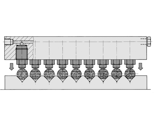
Multiple clamping fixture for clamping of small parts. The cylinders can be arranged in clamping bars or yokes.
This multiple clamping fixture is equipped with threaded-body cylinders with swivel contact bolts. The 3° incline of the threaded-body cylinders effects a low-clamping force of approx. 5 % of the clamping force. On plane clamping surfaces swivel contact bolts obtain little surface pressure on the effective points.
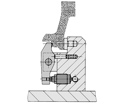
Workholding with the use of reversing levers is particularly suited for workpieces which have to be clamped high above the fixture base plate. The force-loop closed within a limited fixture component space eliminates bending forces from entering the fixture base plate. The reversing lever allows easy adaptation of the lever ratio to the clamping force required.
Take advantage of the free benefits of our login area:
- CAD data download
- Download operating instructions
Welcome back! Log in to your already existing user account.


