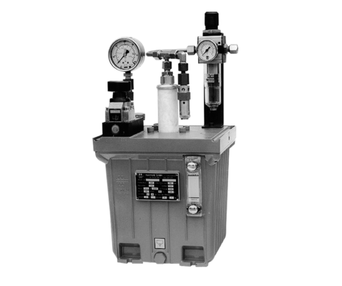
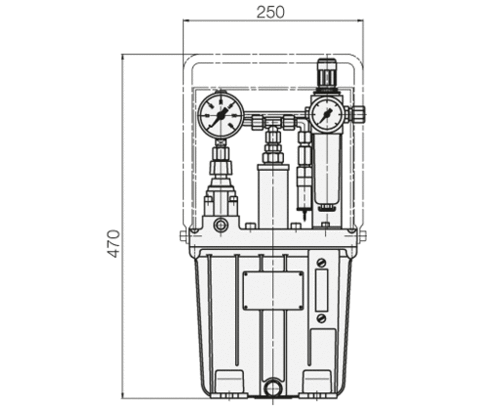
Hydro-Pneumatic Pumps
max. operating pressure 500 bar
Application
The hydraulic clamping pump is particularly suitable for small to medium-sized clamping and assembly fixtures with single-acting cylinders, which operate primarily by intermittence (pressure build up and pressure holding).
Description
The tandem plunger pump is built into the oil reservoir in a space-saving manner. It operates with oscillating movements and automatic stroke reversing control by a pilot-operated 4/2 directional control valve. The stroke frequency and thereby the flow rate depend on air pressure and hydraulic counter pressure.
Control variants
Manually-operated 3/2 directional control valve
This valve is equipped with a turning handle for direct operation at the power unit.
Pneumatically-operated 3/2 directional control valve
This valve is mounted on the power unit allowing for pneumatic remote control, which, however, requires an additional pilot valve (accessory). According to the length of the pneumatic piping between both valves, there is a longer or shorter time delay for the clamping and unclamping operation.
Without valve as pressure generator
For external valve controls (P and R ports only).
The pump unit maintains constant the adjusted pressure.
With attached valve control
For single and double-acting cylinders.
Delivery
The power units are delivered complete and ready for connection. On the pneumatic side there is a service unit with pressure reducer and filter. An additional pressure relief valve prevents increase of pressure over 4.8 bar, and thus operating pressures over 500 bar on the hydraulic side. With valve control fitted, the customer must ensure that the valves are controlled.
| Item no. | CAD data | type | max. operating pressure [bar] | operation | max. flow rate [l/min] | |
|---|---|---|---|---|---|---|
|
Item no.
|
Properties
| |||||
|
Item no.
|
Properties
| |||||
|
Item no.
|
Properties
| |||||
|
Item no.
|
Properties
|
| Item no. | CAD data | Description |
|---|---|---|
|
Item no.
|
Description
Handle
as per data sheet D8.600
|
|
|
Item no.
|
Description
Protection cover
as per data sheet D8.600
|
|
|
Item no.
|
Description
Foot valve with catch
including cover
as per data sheet D8.600
|
|
|
Item no.
|
Description
Hand lever valve with catch
as per data sheet D8.600
|
|
|
Item no.
|
Description
Silencer - size 1/8
as per data sheet D8.600
|
|
|
Item no.
|
Description
Air hose ND 6
as per data sheet D8.600
|
|
|
Item no.
|
Description
Screwed socket G1/4
as per data sheet D8.600
|
|
|
Item no.
|
Description
Hose clamp
as per data sheet D8.600
|
Take advantage of the free benefits of our login area:
- CAD data download
- Download operating instructions
Welcome back! Log in to your already existing user account.

