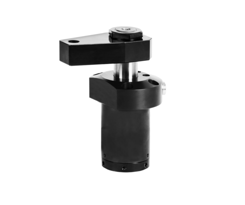
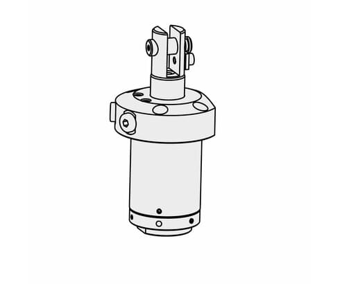
Swing clamps without swing stroke
double acting, max. operating pressure 250 bar

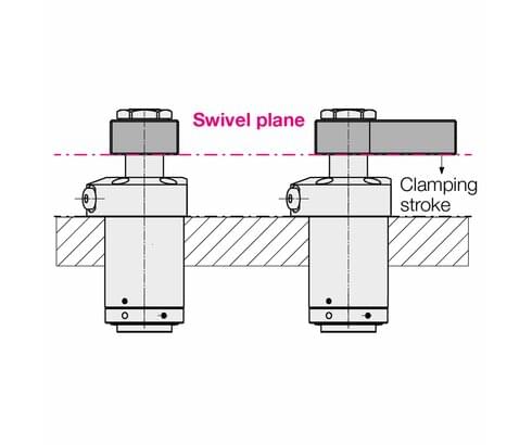
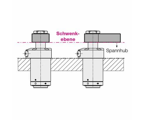
In this version without axial swing stroke, the clamping arm swivels in one plane and does not make any axial movement when swivelled.
Special features
• Reinforced swing mechanism
• Connections for pipe threads and drilled channels
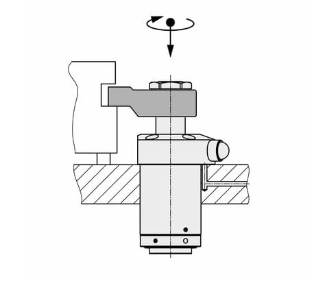
• Radial anti-rotation device in the clamping stroke
• Indexing of clamping arm for repeatable alignment
Reinforced swing mechanism
The reinforced swing mechanism ensures that the angle position of the clamping arm remains the same even if a slight collision with the workpiece during loading and unloading or during clamping occurs.
Radial anti-rotation device in the clamping stroke
With swivelling clamping devices, workpieces can also be machined overhead. In the event of a sudden drop in clamping pressure, the radial anti-rotation device prevents the clamping arm from swivelling back. The workpiece is then no longer clamped. However, a sensible arrangement of several swing clamps and workpiece positioning aids can prevent the workpiece from falling out of the fixture (see also the note in the operating manual).
Advantages
● Compact design partially recessible
● Compact design
● Extremely short clamping and unclamping times
● Swinging in into narrow recesses
● Wiper with metal swarf protection
Versions
• 3 sizes
• Clamping arm seat with cone 1: 10, pendulum eye or fork head
• 2 clamping strokes per size
• Clockwise, counterclockwise or non-swivelling swing motion
• Swing angle 0°, 15° to 75° and 90°
• Angle of clamping position selectable for pendulum eye or fork head
Seals
NBR = nitrile butadiene rubber
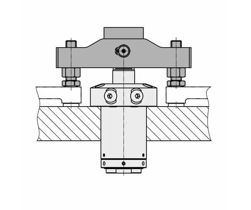
Double clamping arm
This allows space-saving clamping of workpieces in multiple clamping fixtures.
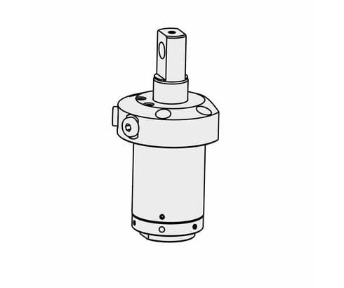
Piston rods with pendulum eyes and fork heads are available so that optimally fitting double clamping arms can be attached.
For a newly designed double clamping arm, the moment of inertia must be determined to
calculate the admissible flow rate using the formula on page 9 of the catalogue sheet.
| Item no. | CAD data | functioning | piston diameter [mm] | rod diameter [mm] | max. pulling force [kN] | |
|---|---|---|---|---|---|---|
|
Item no.
|
CAD data
|
Properties
| ||||
|
Item no.
|
CAD data
|
Properties
| ||||
|
Item no.
|
CAD data
|
Properties
| ||||
|
Item no.
|
CAD data
|
Properties
| ||||
|
Item no.
|
CAD data
|
Properties
| ||||
|
Item no.
|
CAD data
|
Properties
| ||||
|
Item no.
|
CAD data
|
Properties
| ||||
|
Item no.
|
CAD data
|
Properties
| ||||
|
Item no.
|
CAD data
|
Properties
| ||||
|
Item no.
|
CAD data
|
Properties
|
| Item no. | CAD data | Description |
|---|---|---|
|
Item no.
|
Description
O-ring 6 x 1.5 mm, NBR
as per data sheet B1.828
|
|
|
Item no.
|
CAD data
|
Description
O-ring 8 x 1.5 mm, NBR
as per data sheet B1.5091
|
|
Item no.
|
CAD data
|
Description
Clamping arm blank with cone 1:10
for piston rod Ø 16 mm
max. 250 bar, as per data sheet B1.8807
|
|
Item no.
|
Description
Clamping arm blank with cone 1:10
for piston rod Ø 25 mm
max. 250 bar, as per data sheet B1.8807
|
|
|
Item no.
|
CAD data
|
Description
Clamping arm blank with cone 1:10
for piston rod Ø 36 mm
max. 250 bar, as per data sheet B1.8807
|
|
Item no.
|
Description
Nut M14x1.5
as per data sheet B1.852
|
|
|
Item no.
|
Description
Hex nut M22 x 1.5 mm
tightening torque: 50 Nm
as per data sheet B1.8807
|
|
|
Item no.
|
Description
Hex nut M30 x 1,5 mm
tightening torque: 110 Nm
as per data sheet B1.8807
|
|
|
Item no.
|
Description
Index pin Ø3 x 6 mm, St50k
as per data sheet B1.852
|
|
|
Item no.
|
CAD data
|
Description
Dowel pin Ø 3 x 12 mm
as per data sheet B1.8807
|
Bei dieser Ausführung ohne axialem Schwenkhub schwenkt das Spanneisen in einer Ebene und macht beim Schwenken keine Axialbewegung.
Besondere Merkmale
• Verstärkte Schwenkmechanik
• Anschlüsse für Rohrgewinde und gebohrte Kanäle
• Radiale Verdrehsicherung im Spannhub
• Indexierung des Spanneisens zur wiederholgenauen Ausrichtung
Verstärkte Schwenkmechanik
Durch die verstärkte Schwenkmechanik bleibt die Winkelstellung des Spanneisens auch nach einer leichten Kollision beim Be- und Entladen des Werkstücks oder beim Spannvorgang erhalten.
Radiale Verdrehsicherung im Spannhub
Mit schwenkbaren Spannvorrichtungen können Werkstücke auch über Kopf bearbeitet werden. Bei einem plötzlichem Spanndruckabfall wird durch die radiale Verdrehsicherung ein Zurückschwenken des Spanneisens verhindert. Das Werkstück ist dann nicht mehr festgespannt. Durch eine sinnvolle Anordnung mehrerer Schwenkspanner und Werkstückpositionierhilfen kann aber ein Herausfallen des Werkstücks aus der Vorrichtung verhindert werden (siehe auch Hinweis in der Betriebsanleitung).
Vorteile
● Kompakte Bauform teilweise versenkbar
● Kürzeste Baulänge
● Sehr kurze Spann- und Entspannzeit
● Einschwenken in schmale Vertiefungen
● Abstreifer mit metallischem Späneschutz
Ausführungen
• 3 Baugrößen
• Spanneisenaufnahme mit Kegel 1 : 10, Pendelauge oder Gabelkopf
• 2 Spannhübe je Baugröße
• rechts, links oder nicht schwenkend
• Schwenkwinkel 0°, 15° bis 75° und 90°
• Winkel der Spannstellung bei Pendelauge oder Gabelkopf wählbar
Dichtungen
NBR = Nitril-Butadien-Kautschuk
Doppelspanneisen
Damit können in Mehrfachspannvorrichtungen Werkstücke platzsparend gespannt werden. Lieferbar sind Kolbenstangen mit Pendelaugen und Gabelköpfen, sodass optimal passende Doppelspanneisen befestigt werden können. Für ein neu konstruiertes Doppelspanneisen muss das Trägheitsmoment ermittelt werden, um den zulässigen Volumenstrom nach der Formel auf Seite 9 des Katalogblatts zu berechnen.
Take advantage of the free benefits of our login area:
- CAD data download
- Download operating instructions
Welcome back! Log in to your already existing user account.