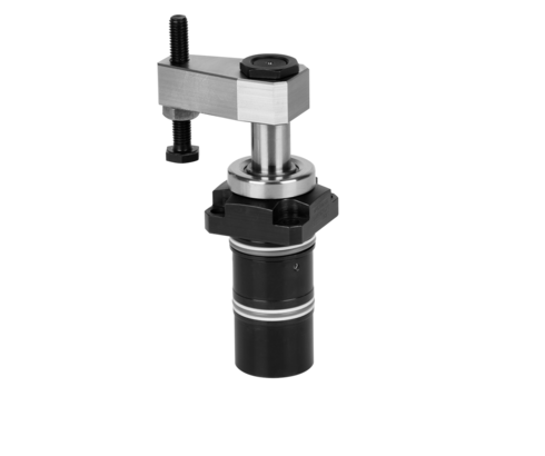
Swing Clamps with Sturdy Swing Mechanism
double acting, max. operating pressure 350 bar
Hydraulic swing clamps are used for clamping of workpieces, when it is essential to keep the clamping area free of straps and clamping components for unrestricted workpiece loading and unloading.
This series obtains very high clamping forces already at 120 bar and can directly be connected to the low-pressure hydraulics of the ma-
chine tool. An additional power unit for power workholding is no longer necessary.
With the sturdy swing mechanism and the optional position monitoring these swing clamps are particularly suitable for:
- Automatic manufacturing systems with very short cycle times
- Clamping fixtures with workpiece loading by handling systems
- Transfer lines
- Test systems for motors, gears and axes
- Assembly lines
- Special machine tools
The hydraulic swing clamp is a pull-type cylinder where a part of the total stroke is used to swing the piston.
Due to the sturdy swing mechanism the angle position of the clamping arm remains the same after a slight collision with the workpiece during loading and unloading or during clamping.
The angle position of the clamping arm is fixed with a dowel pin.
The FKM wiper at the piston rod can be protected against coarse and hot swarf by an optionally available metallic wiper.
The version with extended switch rod is provided for mounting of pneumatic or electrical position monitorings (accessory).
Version without bottom cover
Focusing on a short length, the bottom cover had been omitted. The piston contacts the bottom of the cartridge-type hole.
| Item no. | CAD data | functioning | piston diameter [mm] | rod diameter [mm] | max. pulling force [kN] | |
|---|---|---|---|---|---|---|
|
Item no.
|
CAD data
|
Properties
| ||||
|
Item no.
|
CAD data
|
Properties
| ||||
|
Item no.
|
CAD data
|
Properties
| ||||
|
Item no.
|
CAD data
|
Properties
| ||||
|
Item no.
|
CAD data
|
Properties
| ||||
|
Item no.
|
CAD data
|
Properties
| ||||
|
Item no.
|
CAD data
|
Properties
| ||||
|
Item no.
|
CAD data
|
Properties
| ||||
|
Item no.
|
CAD data
|
Properties
| ||||
|
Item no.
|
CAD data
|
Properties
|
| Item no. | CAD data | Description |
|---|---|---|
|
Item no.
|
CAD data
|
Description
Angle bracket, complete
for series 1843
as per data sheet B1.852
|
|
Item no.
|
CAD data
|
Description
Angle bracket, complete
for series 1844
as per data sheet B1.852
|
|
Item no.
|
CAD data
|
Description
Angle bracket, complete
for series 1845, 1846 and 1847
as per data sheet B1.852
|
|
Item no.
|
Description
Metallic wiper, complete
for rod diameter 32 mm
as per data sheet B1.852
|
|
|
Item no.
|
Description
Metallic wiper, complete
for rod diameter 16 mm
as per data sheet B1.852
|
|
|
Item no.
|
Description
Metallic wiper, complete
for rod diameter 25 mm
as per data sheet B1.852
|
|
|
Item no.
|
CAD data
|
Description
Metallic wiper, complete
for rod diameter 20 mm
as per data sheet B1.852
|
|
Item no.
|
CAD data
|
Description
Pneumatic position monitoring
for manifold-mounting, ND 2 mm
switching range 2 to 9 mm
max. 10 bar, as per data sheet B1.852
|
|
Item no.
|
CAD data
|
Description
Pneumatic position monitoring
for manifold-mounting, ND 2 mm
switching range 2 to 10 mm
max. 10 bar, as per data sheet B1.852
|
|
Item no.
|
CAD data
|
Description
Clamping arm with contact bolt
for series 1843
max. 350 bar, as per data sheet B1.852
|
Take advantage of the free benefits of our login area:
- CAD data download
- Download operating instructions
Welcome back! Log in to your already existing user account.
