Block cylinders

Double-acting block cylinders can be used universally for all hydraulically-operated linear movements.
- Positioning
- Clamping
- Supporting
- Locking
- Bending
- Riveting
- Punching
- Moving
- Opening and closing
- Locking and unlocking
- Lifting and lowering
- Pushing and pulling
The double-acting functioning allows a force generation in both axial directions (force to push and to pull). This guarantees a high function safety as well as exactly calculable and repetitive times required for the stroke.
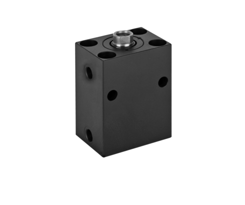
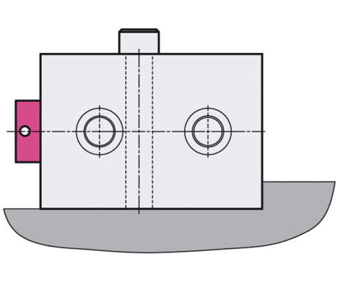
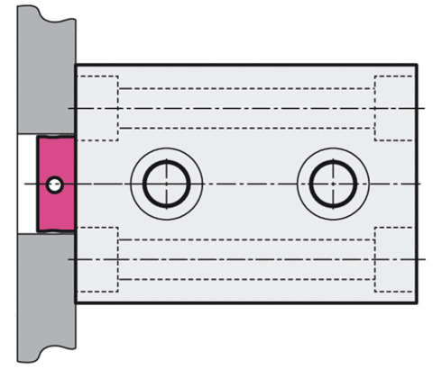
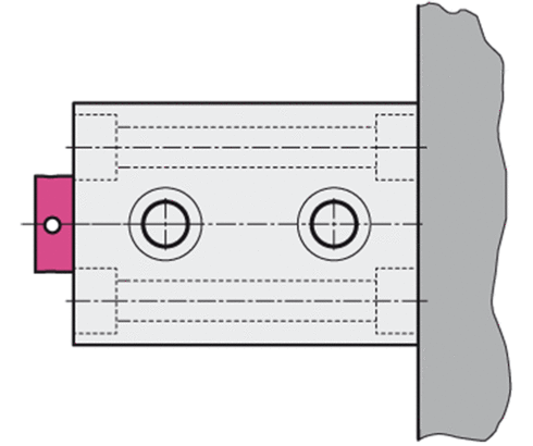
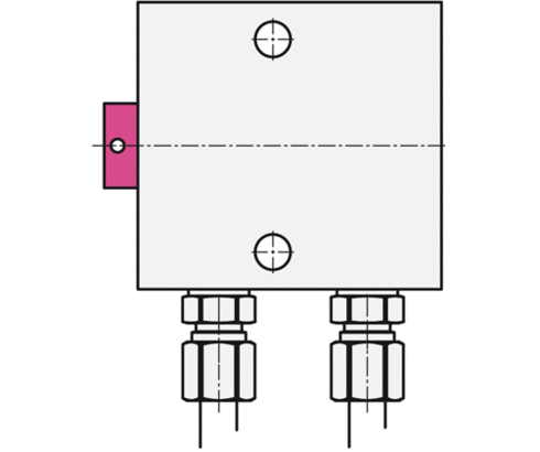
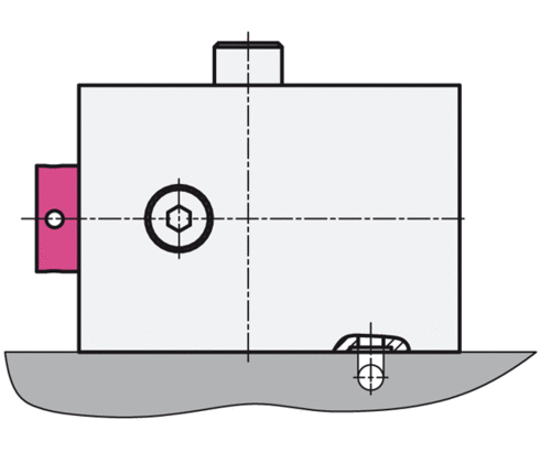
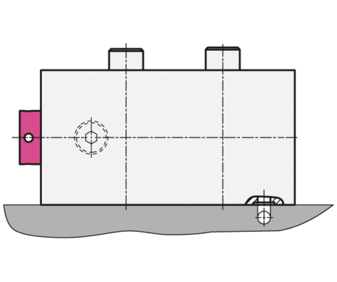
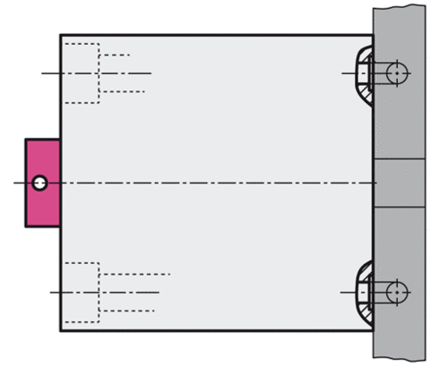
Block cylinders have cross holes and/or longitudinal holes for mounting. For mounting of the block cylinders internal threads can be provided instead of the through holes, optionally at the piston rod side or the bottom side.
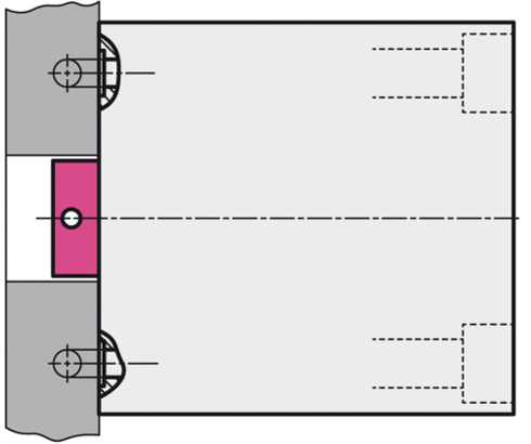
As an alternative to a support, hydraulic block cylinders can be fitted in the housing with a keyway, which transfers the cylinder forces to the baseplate surface via a key.


Connection with pipe thread
Manifold-mounting with O-ring sealing
Manifold-mounting connection K- with 2 mounting holes
Manifold-mounting connection L - with 4 mounting holes
Manifold-mounting connection S- with 4 mounting holes
Manifold-mounting connection B- with 4 mounting holes
Stroke limitation by distance bushing: Economical and quickly supplied intermediate strokes
A distance bushing is inserted on the piston rod side in the standard cylinder with the next largest stroke and fastened inside the housing. That means the piston can no longer complete the extending stroke and the stroke is restricted by this internal stop, dependent on the length of the bushing.

| Item no. | CAD data | type | stroke [mm] | functioning | stroke end cushioning | |
|---|---|---|---|---|---|---|
|
Item no.
|
CAD data
|
Properties
| ||||
|
Item no.
|
CAD data
|
Properties
| ||||
|
Item no.
|
CAD data
|
Properties
| ||||
|
Item no.
|
CAD data
|
Properties
| ||||
|
Item no.
|
CAD data
|
Properties
| ||||
|
Item no.
|
CAD data
|
Properties
| ||||
|
Item no.
|
CAD data
|
Properties
| ||||
|
Item no.
|
CAD data
|
Properties
| ||||
|
Item no.
|
CAD data
|
Properties
| ||||
|
Item no.
|
CAD data
|
Properties
|
| Item no. | CAD data | Description |
|---|---|---|
|
Item no.
|
CAD data
|
Description
Contact bolt M16 x 20 mm
dome head
as per data sheet G3.800
|
|
Item no.
|
CAD data
|
Description
Contact bolt M20 x 25 mm
dome head
as per data sheet G3.800
|
|
Item no.
|
CAD data
|
Description
Contact bolt M6 x 10 mm
dome head
as per data sheet G3.800
|
|
Item no.
|
CAD data
|
Description
Contact bolt M27 x 30 mm
dome head
as per data sheet G3.800
|
|
Item no.
|
CAD data
|
Description
Contact bolt M30 x 35 mm
dome head
as per data sheet G3.800
|
|
Item no.
|
CAD data
|
Description
Contact bolt M42 x 45 mm
dome head
as per data sheet G3.800
|
|
Item no.
|
CAD data
|
Description
Contact bolt M48 x 60 mm
dome head
as per data sheet G3.800
|
|
Item no.
|
CAD data
|
Description
Contact bolt M10 x 12 mm
cone head
as per data sheet G3.800
|
|
Item no.
|
CAD data
|
Description
Contact bolt M16 x 20 mm
cone head
as per data sheet G3.800
|
|
Item no.
|
CAD data
|
Description
Contact bolt M20 x 25 mm
cone head
as per data sheet G3.800
|
- Double acting
- Single acting


Take advantage of the free benefits of our login area:
- CAD data download
- Download operating instructions
Welcome back! Log in to your already existing user account.