Block cylinders
double acting, max. operating pressure 350 bar or 500 bar
Hydraulic block cylinders are universally used for all linear movements with high force requirements and very small dimensions. With the adjustable magnetic sensors certain
piston positions can be controlled exactly.
The double-acting function ensures high function safety as well as exactly calculable and repeatable stroke times.
The piston of these block cylinders is equipped with a ring-shaped magnet whose magnetic field actuates the sensor.
The cylinder housing is therefore made of a non-magnetisable material.
Two variants are available:
- 154X X1X: High-tensile aluminium alloy max. operating pressure 350 bar
- 154X X5X: High-tensile bronze alloy max. operating pressure 500 bar
The magnetic sensors are guided in dovetail slots and allow a continuous control of the piston position.
| Item no. | CAD data | type | stroke [mm] | functioning | stroke end cushioning | |
|---|---|---|---|---|---|---|
|
Item no.
|
CAD data
|
Properties
| ||||
|
Item no.
|
CAD data
|
Properties
| ||||
|
Item no.
|
CAD data
|
Properties
| ||||
|
Item no.
|
CAD data
|
Properties
| ||||
|
Item no.
|
CAD data
|
Properties
| ||||
|
Item no.
|
CAD data
|
Properties
| ||||
|
Item no.
|
CAD data
|
Properties
| ||||
|
Item no.
|
CAD data
|
Properties
| ||||
|
Item no.
|
CAD data
|
Properties
| ||||
|
Item no.
|
CAD data
|
Properties
|
| Item no. | CAD data | Description |
|---|---|---|
|
Item no.
|
Description
O-ring 8 x 1.5 mm, FKM
as per data sheet B1.5091
|
|
|
Item no.
|
Description
O-ring 12.42 x 1.78 mm - NBR
as per data sheet B1.554
|
|
|
Item no.
|
CAD data
|
Description
O-ring 7 x 1.5 mm, NBR
as per data sheet B1.5091
|
|
Item no.
|
CAD data
|
Description
O-ring 8 x 1.5 mm, NBR
as per data sheet B1.5091
|
|
Item no.
|
CAD data
|
Description
O-ring 7 x 1.5 mm, FKM
as per data sheet B1.5091
|
|
Item no.
|
Description
O-ring 12.42 x 1.78 mm - FKM
as per data sheet B1.554
|
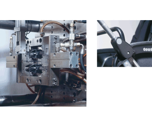
Tools for fabrication of connecting elements for prams
The core-pullers for injection moulding connecting components made out of plastic materials are inserted and retracted by aluminium block cylinders B1.554 for fabrication in exact position.
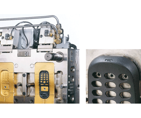
Tool for fabrication of mobile phone housings
The exact shaping of the inlet for the later installation of the microphone is made during the injection process by dies, which are operated by aluminium block cylinders with magnetic sensors.
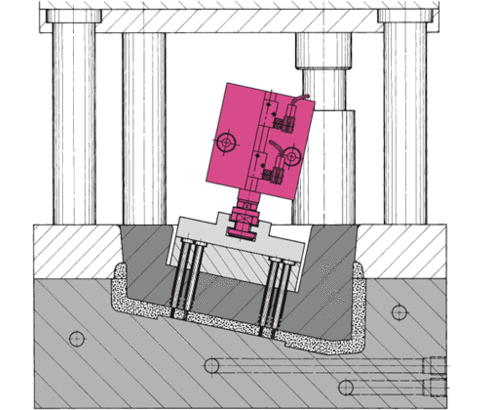
Operating core pins
In the figure the core cylinder is located in the main core. The position monitoring supplies the required information about the position of the core pins.
The connection of cylinder and core puller should be effected by means of a coupling pin, because core pullers are usually self-guiding.
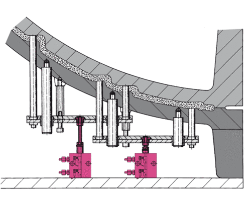
Operating core puller plates
The figure shows an item which is made in three versions. The core-pins are driven into the corresponding position by two independently-controlled core puller plates.
Version A core puller plate 1 actuated
Version B core puller plate 2 actuated
Version C core puller plates 1+2 actuated
The core puller plates drive against fixed stops in the front and back position
and are controlled by proximity switches in both positions. This enables an integration into the control of the mould carrier.
The figure shows version A;
Core puller plate 1 is actuated.
Core puller plate 2 is not actuated.
The building height of the foam mould is limited by the mould carrier.
Due to the small and compact dimensions of the block cylinders the core puller plates could be installed in a space-saving way.
Take advantage of the free benefits of our login area:
- CAD data download
- Download operating instructions
Welcome back! Log in to your already existing user account.


