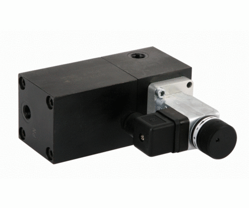
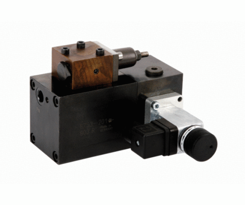
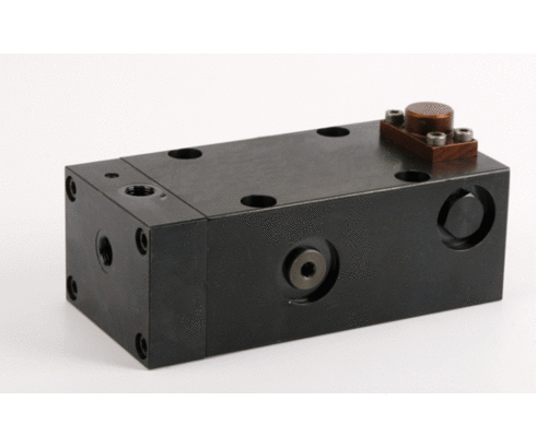
Intensifier 21 cm³
max. operating pressure 500 / 125 bar
single and double acting
Application
Hydraulic intensifiers convert a hydraulic pressure on the primary side (input) into a higher pressure on the secondary side (output). This enables the use of the comparatively low pressure of machine tool hydraulics to pressurise a hydraulic cylinder with increased pressure.
The oil quantity to be transmitted is not important for the intensifiers of this data sheet. Only after oil supply of the hydraulic cylinder in the low-pressure range is affected, the piston of intensification will be activated according to its specification by an external valve control or by an integrated switching function.
Important notes
The intensification volume of intensifiers is 21 cm³. This is the reason why no hydraulic element, which functions only with high pressure, e.g. hydraulic accumulators with a gas-preload pressure of more than100 bar and an oil absorption exceeding 10 cm³, must be used in the high-pressure range. The intensification volume of 21 cm³ is only used to generate the high-pressure, i.e. the compressibility of the hydraulic oil (1% at a pressure increase of 150 bar) and the increase of volume of the high-pressure hoses (1cm³ per m at a pressure increase of 100 bar) has to be considered.
Complete air bleeding of the hydraulic system is very important.
The high-pressure part should be controlled by a pressure gauge.
The elements 8753 200, -201 and -203 can be equipped with a manifold-mounted pressure switch for machine tool interlock, when using 8753-202 the pressure switch will be integrated in the piping. The switching pressure should be adjusted to 80 % of the secondary pressure.
When using pressure intensifiers 8753 201 and 8753 202 pay attention that no liquids penetrate through venting port “Z”. The vent screw with sintered metal air filter can be removed and a vent hose can be connected, if required.
Operating conditions, tolerances and other data see data sheet A 0.100.
Versions
- double-acting intensifier for single-acting cylinders
- double-acting intensifier with sequence valve for double-acting cylinders
- single-acting intensifier with integrated sequence valve for single-acting cylinders
| Item no. | CAD data | type | type | functioning | hydraulic port | |
|---|---|---|---|---|---|---|
|
Item no.
|
CAD data
|
Properties
| ||||
|
Item no.
|
CAD data
|
Properties
| ||||
|
Item no.
|
CAD data
|
Properties
| ||||
|
Item no.
|
CAD data
|
Properties
|
| Item no. | CAD data | Description |
|---|---|---|
|
Item no.
|
CAD data
|
Description
Input plate
max. 500 bar, as per data sheet C2.360
|
|
Item no.
|
CAD data
|
Description
Series mounting plate
for 1 directional control valve
max. 500 bar, as per data sheet C2.360
|
|
Item no.
|
Description
Series mounting plate
for 2 valves
as per data sheet D8.753
|
|
|
Item no.
|
CAD data
|
Description
Sequence valve ND 4 - G1/4
with check valve
adjustment range: 10 to 150 bar
max. 500 bar, as per data sheet C2.954
|
|
Item no.
|
CAD data
|
Description
Plug-type connector ND5 - Ø10 x 14 mm
short version, with FKM seals
max. 500 bar, as per data sheet F9.300
|
|
Item no.
|
CAD data
|
Description
Pressure switch, hydro-electric
pressure adjustment range: 50-550 bar
hydraulic connection: manifold mounting
electrical connection: for plug
max. 600 bar, as per data sheet F9.732
|
Take advantage of the free benefits of our login area:
- CAD data download
- Download operating instructions
Welcome back! Log in to your already existing user account.


