Automatic coupling system
max. operating pressure 500 bar
General information
Efficiency of flexible manufacturing systems and quality of workpieces are increased by hydraulically-operated fixtures which can be automatically connected to and disconnected from the power source.
Coupling systems which were designed for that purpose can be used in combination with changing pallets for single and double-acting elements and also for several clamping circuits with a max. operating pressure of 500 bar. Retrofitting is possible.
Clamped fixtures which are disconnected from the power unit can be monitored from time to time by a control cylinder in connection with signal switches or continuously by infra-red pressure monitoring.
Description
Each coupling system consists of a coupling unit and the corresponding coupling nipple unit.According to the application, several components can be added to the coupling system that meet different safety requirements.
Design
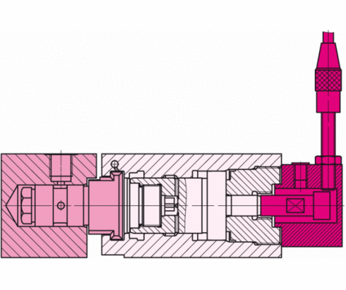
The coupling unit contains the real coupling element which is integrated in the coupling piston. The coupling piston extends or retracts for coupling and uncoupling, respectively. The front of the coupling element is flat and therefore allows easy cleaning. At each standard version the uncoupled position of the coupling piston can be controlled by inductive proximity switches or by electro-pneumatic differential pressure switches, depending on the corresponding version. For controlling the coupled mode, a second switch is required. At the pressure side of the coupling nipple unit a non-return valve is installed and at the pressureless side a double
check valve with a pre-tension of 6 bar is installed. This double check valve works only in uncoupled mode and prevents the pressure to increase in the return line, if there is an internal leakage in the clamping system. The insertion nipples in the nipple unit allow a radial misalignment adjustment of ±O.5 mm and an axial misalignment adjustment of ±1 mm.
Function (double acting)
Positioning of the coupling nipple unit is made by lateral insertion into the T-slot-type claw of the coupling unit.
When port A1 and A2 are pressurised, the coupling pistons extend. After the coupling pistons are extended, the check valves in the coupling nipple unit and the coupling piston are opened. Both check valves can be opened against system pressure. Oil supply is made through port A and B. To disengage coupling ports B1 and B2 are pressurised. The proximity switches register the retracted position of the coupling positions. Due to safety reasons the coupling unit is operated by means of a so-called differential system, i.e. port B1 and B 2 are not controlled by a valve and are directly connected to the pump.
| Item no. | CAD data | max. operating pressure [bar] | component | nominal diameter [mm] | application for | |
|---|---|---|---|---|---|---|
|
Item no.
|
CAD data
|
Properties
| ||||
|
Item no.
|
CAD data
|
Properties
| ||||
|
Item no.
|
Properties
| |||||
|
Item no.
|
CAD data
|
Properties
| ||||
|
Item no.
|
CAD data
|
Properties
| ||||
|
Item no.
|
CAD data
|
Properties
| ||||
|
Item no.
|
CAD data
|
Properties
| ||||
|
Item no.
|
CAD data
|
Properties
|
| Item no. | CAD data | Description |
|---|---|---|
|
Item no.
|
CAD data
|
Description
Insertion nipple
for double-acting elements
as per data sheet F9.426
|
|
Item no.
|
CAD data
|
Description
Insertion nipple
for single-acting elements
as per data sheet F9.426
|
|
Item no.
|
CAD data
|
Description
Subassembly control cylinder
as per data sheet F9.426
|
|
Item no.
|
CAD data
|
Description
Subassembly limit switch
as per data sheet F9.426
|
|
Item no.
|
CAD data
|
Description
High-pressure shut-off valve ND6
ports G1/4
max. 500 bar, as per data sheet C2.940
|
|
Item no.
|
CAD data
|
Description
Inductive proximity switch M8x1 mm
type A, standard
as per data sheet B1.552
|
|
Item no.
|
CAD data
|
Description
Connecting cable
with straight pnp plug M12
without LED, cable length 3m
as per data sheet G2.140
|
|
Item no.
|
Description
Power unit
single-acting elements
as per data sheet F9.426
|
|
|
Item no.
|
Description
Power unit
double-acting elements
as per data sheet F9.426
|
|
|
Item no.
|
CAD data
|
Description
Hydraulic accumulator 75 ccm
gas preload pressure: 100 bar
port: G1/4 interior thread
max. 500 bar, as per data sheet F9.601
|
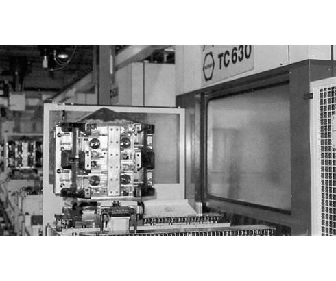
Automatic coupling system for double-acting clamping elements
With control cylinder for pressure monitoring of uncoupled clamping fixtures. Each clamping fixture is allocated to a loading and unloading station with coupling system. The coupling nipple unit is integrated into the fixture body with a minimum use of space.
The maximum operating pressure is approx. 300 bar. This pressure can be controlled at the control cylinder (adjustment range 90-500, hysteresis approx. 15%). 28 fixture pallets are used on 8 machining centres. The clamping pressure is maintained statically after pressurising i.e. during machining of the workpiece there is no connection to the pressure generator.
Take advantage of the free benefits of our login area:
- CAD data download
- Download operating instructions
Welcome back! Log in to your already existing user account.

