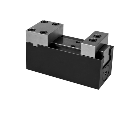
Hydraulic Vises, Long Stroke
max. operating pressure 250 bar
Application
Hydraulic vises, also called fixture clamps, are used for machining of dimensionally stable workpieces in single or multiple clamping fixtures. Due to their compact design they can be arranged in a very limited space. Hydraulic vises are especially suitable for series manufacturing in automated mode.
The double-acting cylinder function combined with central lubrication and good swarf protection guarantees high process safety.
Description
The hydraulic vise with fixed jaw consists of a very small base body with integrated hydraulic cylinder which actuates the movable jaw. All threads and ports are at the bottom to enable a space-saving arrangement of several clamping points in a very limited space. If fixing from below is not possible, an adaptor plate for manifold mounting or tube connection is available.
Blanks of clamping jaws that can be adapted to the workpiece contour are also available as an accessory. The fixed jaw can be equipped with a pneumatic seat check.
Important notes
The hydraulic vise is only suitable for exterior clamping.
Lubricate at the latest after 500 clamping cycles the clamping slide via the central lubrication.
Never use the complete clamping stroke to guarantee safe clamping of the workpiece.
Max. operating temperature 80 °C.
Operating conditions and other data see data sheet A 0.100.
| Item no. | CAD data | functioning | max. operating pressure [bar] | seals | hydraulic ports | |
|---|---|---|---|---|---|---|
|
Item no.
|
CAD data
|
Properties
| ||||
|
Item no.
|
CAD data
|
Properties
|
| Item no. | CAD data | Description |
|---|---|---|
|
Item no.
|
CAD data
|
Description
Adaptor plate
for hydraulic vise 4413-031
max. 250 bar, as per data sheet I4.112
|
|
Item no.
|
CAD data
|
Description
Fixed jaw 40 mm
version: Clamping jaw (blank)
material: 16 MnCr5 soft
as per data sheet I4.112
|
|
Item no.
|
CAD data
|
Description
Adaptor plate
for hydraulic vise 4413-131
max. 250 bar, as per data sheet I4.112
|
|
Item no.
|
CAD data
|
Description
Socket head cap screw M8 x 25 - 12.9
as per data sheet I4.112
|
|
Item no.
|
Description
Socket head cap screw M8 x 25 - 8.8
as per data sheet I4.112
|
|
|
Item no.
|
CAD data
|
Description
Fixed jaw 65 mm
version: Clamping jaw (blank)
material: 16 MnCr5 soft
as per data sheet I4.112
|
|
Item no.
|
Description
O-ring 8 x 1.5 mm, FKM
as per data sheet B1.5091
|
|
|
Item no.
|
Description
Socket head cap screw
M6 x 20 mm - 8.8
as per data sheet I4.120
|
|
|
Item no.
|
CAD data
|
Description
Socket head cap screw M6 x 16 - 12.9
as per data sheet I4.120
|
|
Item no.
|
CAD data
|
Description
Clamping jaw 40 mm
version: Clamping jaw (blank)
material: 16 MnCr5 soft
as per data sheet I4.120
|
Take advantage of the free benefits of our login area:
- CAD data download
- Download operating instructions
Welcome back! Log in to your already existing user account.

